

Product Specifications:
Download 2300 Series Sales Brochure
Note: Installation Guides and Modbus supplementary manuals can be found below for each 2300 series model.
View 2300 Series information from the MicroScan V5 Online Help Manual
Note: The MicroScan V5 Help Manual is automatically installed with MicroScan V5.
Download IOStudio Modbus Configuration Software
Please Note:The IOStudio Modbus Configuration Software is NOT required when using the 2300 series I/O stations with MicroScan V5 software.

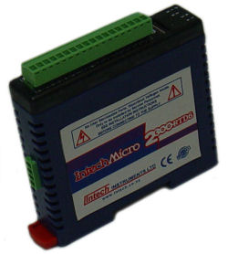
The Intech Micro 2300 series is a system of modular I/O Remote Stations, that add an even lower cost option to Intech’s already extensive intelligent I/O Remote Station family, which connect automatically to the Intech MicroScan V5 logging plus SCADA software package.
The 2300 series I/O stations are made up of stand-alone Digital and Analogue—Input/Output stations.
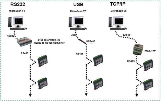
Communications between the computer running MicroScan V5 and the 2300 series stations is RS485 (1 pair cable) multi drop as standard with an option for TCP.
A 32bit ARM CPU is used in the 2300 series stations to provide high speed data processing and fast communications turn around times. All 2300 series stations have been equipped with status led’s which are used to indicate the status of the Inputs or Outputs. This visual indication assists with fault finding and diagnostics.
All the I/O stations clip directly onto an industry standard DIN rail. All stations have a minimum isolation of 1000Vac rms between the field and logic.
Model |
Description and Features |
Download |
| 2300-A8I | 8 x 4~20mA inputs, single ended (all input negatives internally connected) 0~20mA inputs programmable 250 ohms input resistance 1.5KV isolation between inputs and power supply and comms (RS485) Power Supply = 24Vdc @ 30mA typical Requires an independent and isolated power supply to power logic inputs |
|
| 2300-A8II | 8 x 4~20mA inputs, Isolated 1.0KV isolation between each input 0~20mA inputs programmable 250 ohms input resistance 1.5KV isolation between inputs and power supply and comms (RS485) Power Supply = 24Vdc @ 40mA typical |
|
| 2300-A8VI | 8 x Voltage inputs, Isolated 1.0KV isolation between each input 0~10V or 2~10V inputs programmable 20 Kohms input resistance 1.5KV isolation between inputs and power supply and comms (RS485) Power Supply = 24Vdc @ 40mA typical |
|
| 2300-Tc8 | 8 x Thermocouple & mV inputs, Isolated 350V peak isolation between each input Programmable inputs type K, J, T, E, N, B, S, R, with CJC Programmable mV inputs 0~50mV, -100~100mV 1.5KV isolation between inputs and power supply and comms (RS485) Power Supply = 24Vdc @ 40mA typical |
|
| 2300-RTD6 | 6 x RTD inputs, Pt100, Pt1000, Ni120, Ni1000 1.5KV isolation between inputs and power supply and comms (RS485) Resolution = 0.1°C Power Supply = 24Vdc @ 55mA typical |
|
| 2300-MULTI | 6 x combination analogue inputs, single ended 2 x RTD inputs, 2 x 4~20mA inputs, 2 x Voltage inputs, 1 x 4~20mA output, 4 x Digital inputs, 2 x Digital outputs 1.5KV isolation between inputs and power supply and comms (RS485) Power Supply = 24Vdc @ 70mA typical |
|
| 2300-D16 | 16 x Digital inputs Input voltage: 12~24Vdc 1.5KV isolation between inputs and power supply and comms (RS485) Power Supply = 24Vdc @ 30mA typical |
|
| 2300-RO4 | 4 x Relay outputs Change over contacts Contact rating: 240Vac @ 0.5A 28Vdc @ 1A 1.0KV isolation between inputs and power supply and comms (RS485) One output can be dedicated to Comms Fail Alarm Power Supply = 24Vdc @ 100mA typical |
|
| 2300-AO8I | 8 x 4~20mA outputs, single ended (all output negatives internally connected) 0~20mA outputs programmable 1.5KV isolation between outputs and power supply and comms (RS485) Power Supply = 24Vdc @ 18mA typical Requires an independent and isolated power supply to power logic outputs = 24Vdc @ 175mA typical |
Modbus Manual |
| 24V DC Power Supply Options: | ||
| PSW-2-F | Output Voltage: 24Vdc Max current: 200mA continuous Input Power Supply: 85~265Vac/dc |
Installation Guide |
| PSW-10-X | Output Voltage: 24Vdc Max Current: 1 Amp continuous Input Power Supply: 100~264Vac/dc |
Installation Guide |
| RS485 Comms Converter Options: | ||
| 2100-IS | RS232 to RS485 Isolating converter. Comms baud rate: 9600 Relay output: 1 relay, change over. Rating, 1 amp, 24Vdc. Power supply: 9V plug pack (supplied with 2100-IS). Internal audible and relay output alarm for communication failure. |
Installation Guide |
| 2100-NS | RS232 to RS485 converter kit. Non-isolating. Comms baud rate: 9600 Power supply: 9 volt plug pack (supplied with 2100-NS). |
Installation Guide |
| USB485 | USB to RS485 converter. Non-isolating. Powered from computer USB port. 3m length. Note: Only use the USB485 for temporary monitoring situations; for industrial environments we recommend using a physical RS232 connection. |
Installation Guide |
| 2300-NET | Ethernet TCP/IP to RS485 Converter. Isolating. Comms baud rate: 9600 Power supply: 24Vdc Modbus TCP to Modbus RTU Compact DIN rail mount Enclosure The PSW-2-X can be supplied with the 2300-NET if you require a 24Vdc Power supply. Note: For connecting via Ethernet, the 2300-NET is used with the 2300 series I/O Remote Stations. For the 2100 series I/O Remote Stations and Shimaden Controllers use the 2100-NET. |
|

2300-NET
